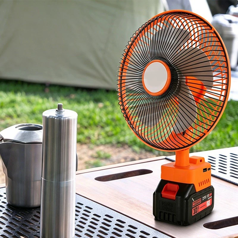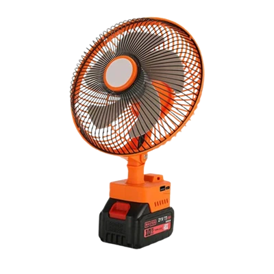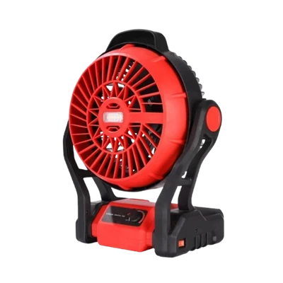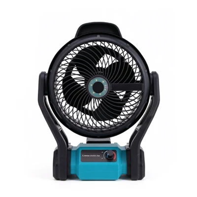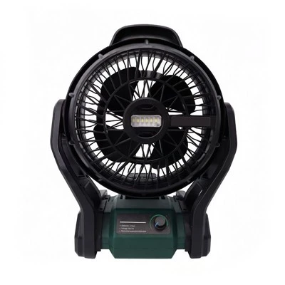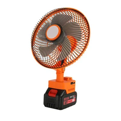

The emergency fan's control unit uses a primary control chip as its intelligent control center, integrating power circuits connected to external AC power, charging control circuits connected to the battery, motor control and speed control circuits connected to the motor, AC/DC automatic conversion control circuits, and lighting control circuits connected to the lighting fixture. Its internal core chip primarily handles lithium battery charging, DC motor and stepper motor driving, backlight control, and button input control.
The emergency fan has a built-in 3.7V 18650 lithium battery pack with a protection board, charged via a USB Type-C 6-pin female connector, which supports over 5A high-current charging. Charging management of individual lithium-ion batteries is typically handled by a constant-current/constant-voltage linear charger like the CL4056D.
The fan's drive section includes a DC motor for speed control and a four-phase five-wire 5V stepper motor for oscillation. The microcontroller unit controlling these motors is presumably a domestically produced 8-bit microcontroller with multiple I/O control ports or PWM outputs to achieve intelligent control functions such as PWM speed regulation of the brushless motor, remote control, and lighting.
The latest patented technology focuses on optimizing fan structure. One type of rechargeable fan with adjustable airflow incorporates a protective shell and spring plates on the outside of the fan housing for shock absorption. The fan direction is changed by twisting a lever to engage gears and toothed grooves. Wireless charging fans utilize electromagnetic induction technology, facing the challenge of combined charging heat generation and motor heat dissipation. Solutions include optimizing the electromagnetic coupling structure, employing a composite heat dissipation design, and introducing a temperature control system to dynamically adjust power. Regarding airflow optimization, by placing a first stationary blade within the fan assembly or mounting base, and a second stationary blade at the air outlet, the airflow is guided and rectified, ensuring a more uniform and stable discharge. Motor performance is improved by making the axial length of the magnets in the rotor assembly greater than the total thickness of the multiple stacked magnetic components in the stator assembly, thereby reducing magnetic leakage and increasing magnetic flux utilization, effectively enhancing motor performance.